
 Sign In

 Shop
Shop

 Academy
iPhone X Won't Charge? Here is the Fix!
Our repair case today is about repairing an iPhone X that won’t charge but with the lightning bolt showing up.
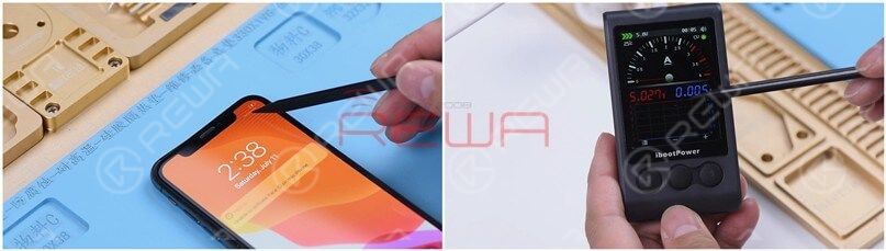
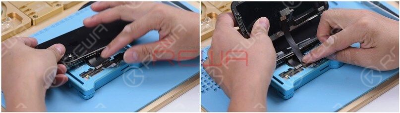
First of all, let’s get the motherboard installed and test. The phone turns on normally. Plug the charging cable and the lightning bolt shows up. However, there is no charging current on the ammeter. Judging by this, the motherboard can detect the power adapter whereas the phone won’t charge.
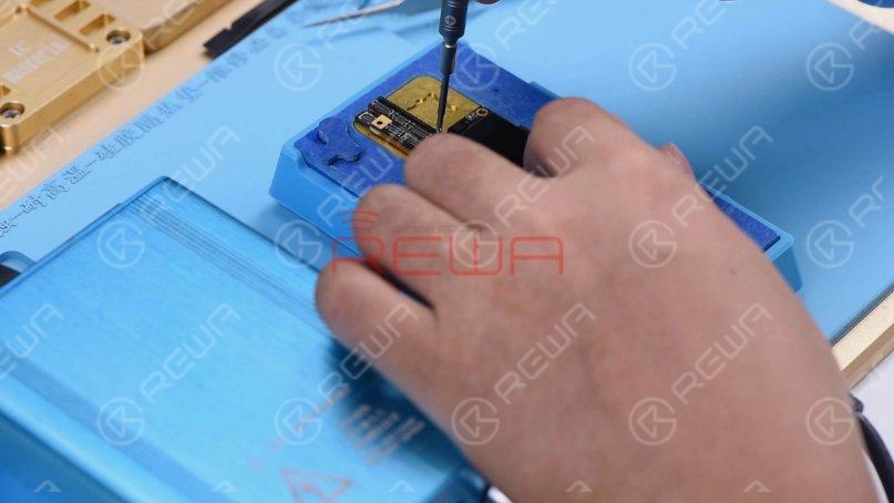
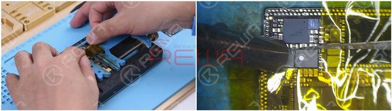
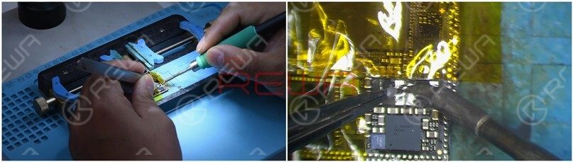
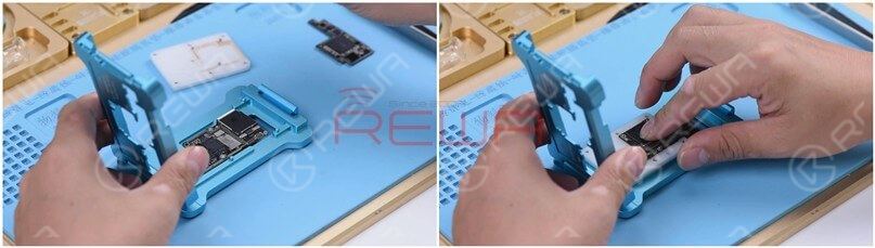
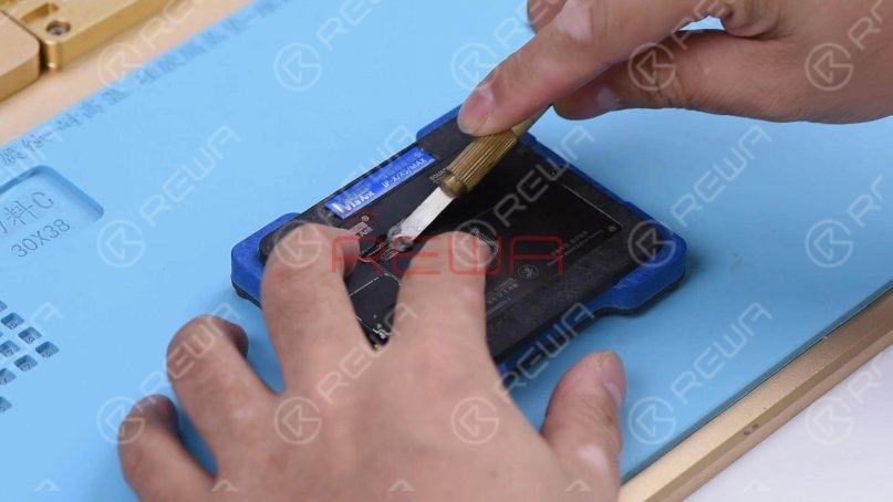
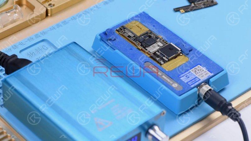
Since the housing, the battery, and the charging port flex cable used for the test are known-good parts, we need to focus on the charging circuit on the motherboard. The first thing we need to do is to separate the upper layer from the lower layer. Place the motherboard on the heating platform and fit a screw into the screw hole on the motherboard. So we can take down the upper layer efficiently afterward. Heat the motherboard for 2 minutes on the heating platform at 165℃.
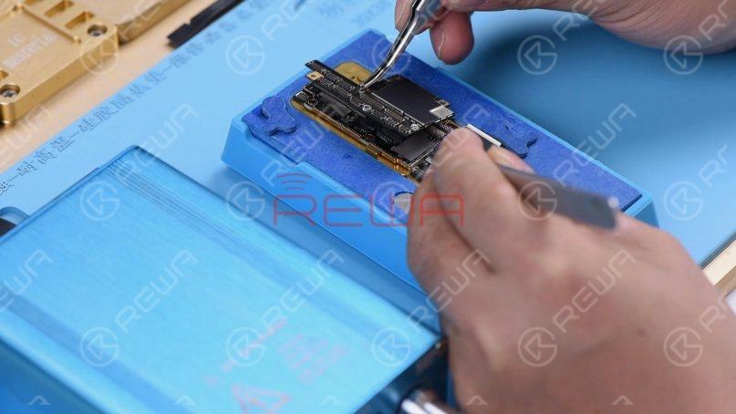
Remove the upper layer and lower layer with tweezers.
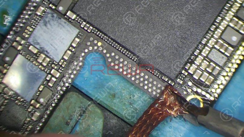
Run diode mode measurement of Pin 2 and Pin 3 on the battery connector J3200. The measured value is normal.
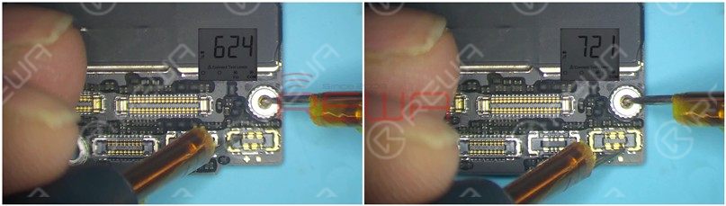
Continue measuring TIGRIS_LX between charging IC U3300 and Q3350. The measured value is 250, which is abnormal. The normal value should be 0. Judging by the measured value, TIGRIS_LX has open-circuited.
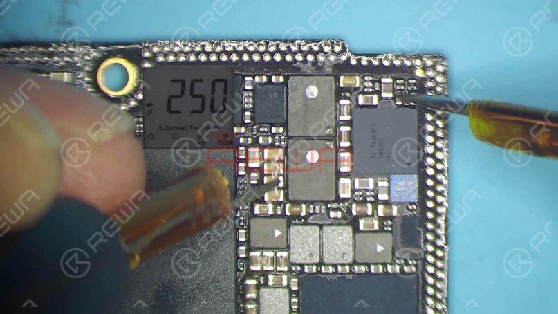
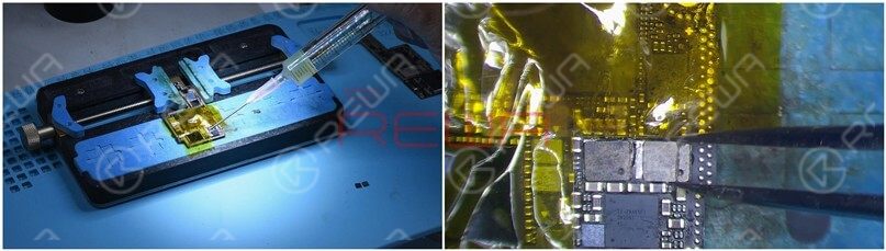
L3341 and L3340 are connected in series on the circuit. The open-circuited condition indicates that the two inductors might have been pseudo soldered or damaged. We need to replace the two damaged inductors with new inductors. Attach the upper layer to the PCB holder and stick high-temperature tape on components around. Heat with QUICK 990AD Hot Air Gun at 300℃ and airflow 3. Remove black adhesive around the two inductors.
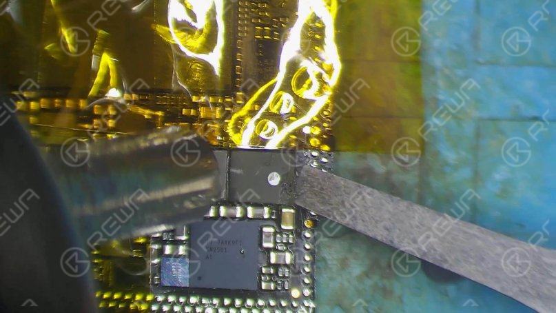
Once done, apply some paste flux to the two inductors. Heat with Quick 990AD Hot Air Gun at 360℃ and airflow 3.
Pry up the two inductors carefully with the pry knife.
Continue to apply some medium-temp solder paste to the two bonding pads. Tin the two bonding pads with Soldering Iron at 365℃. Then clean black adhesive on the bonding pad.
Continue to apply some paste flux to the two bonding pads. Get the two inductors in the right position, and solder with QUICK 990AD Hot Air Gun at 360℃ and airflow 3.
Clean with PCB cleaner afterward. Again, let’s run diode mode measurement of TIGRIS_LX between U3300 and Q3350. The measured value is 0, which is normal.
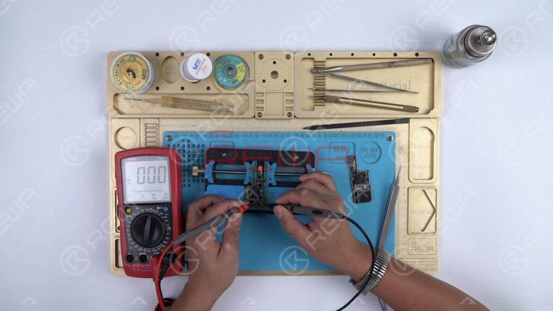
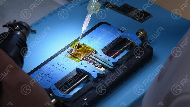
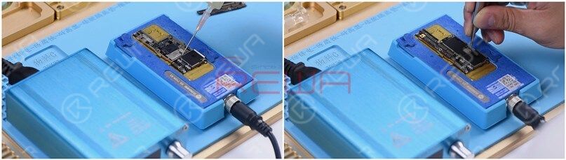
Now we need to attach the upper layer and the lower layer to the testing fixture and test. Firstly, clean the bonding pad.
Then attach the upper layer and the lower layer to the testing fixture.
Get the charging port flex cable connected. Then get the screen and the battery connected.
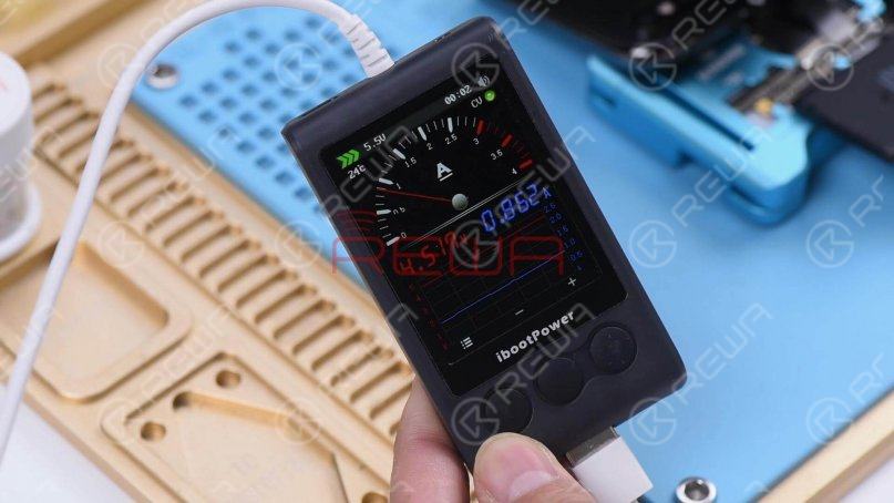
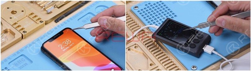
Plug the charging cable. The charging current on the ammeter is 860mA, which indicates that the phone can be normally charged.
The next thing we need to do is to solder the two layers together. We need to get the lower layer reballed first. Put the lower layer into the reballing mold and get the BGA Reballing Stencil in position.
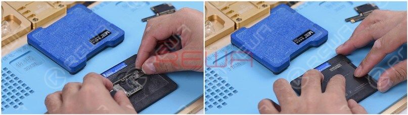
Place the mold onto the base. The stencil is tightly attached to the lower layer because of the magnetic structure of the base. Then we smear some low-temp solder paste on the stencil and wipe off excess solder paste with a lint-free wipe.
After reballing, take the mold down from the base and remove the reballing stencil. Heat the lower layer on the heating platform at 165℃. Once solder balls have shaped up completely, power off the heating platform.
Cool for 5 minutes. Apply some BGA Paste Flux to the bonding pad and get the upper layer in position. Then power on the heating platform. With the temperature reaching 165℃, continue heating for 2 minutes.
Turn the power off and cool for 5 minutes. Then take down the motherboard from the heating platform. Please check carefully to make sure that the two layers have been soldered together perfectly. Now we can assemble the phone and test. Get the motherboard installed and display assembly connected. Plug the charging cable. The lightning bolt shows up on the screen. The charging current on the ammeter is also normal. The fault is cleared.
Summary
The lightning bolt shows up on the iPhone X screen while there is no charging current on the ammeter. Check the charging circuit on the motherboard and one rail has open-circuited. Replace the two inductors on the rail and the problem is fixed.
If you are looking for more in-depth content and want to study systematically, please feel free to visit our academy.


No Comments
1
0
Share
Apr 23, 2021
ABOUT REWA
REWA is a world leading electronics repair business solutions provider who was founded in 2008 in HongKong. We are committed to delivering one-stop services covering Sourcing Solution, Technical Support Solution as well as Recycle & Resell Solution.


